

Description
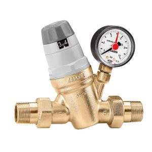
When mains pressure climbs above the range a building’s pipework was designed for, the fittings are the first to report it: dripping taps, banging pipes, flexible connectors that fail early. A pressure reducing and control set removes that load at the service entry.
A pressure reducing valve is a self-acting device that holds a set outlet pressure largely independently of what happens upstream. A diaphragm or piston inside it continuously compares the force produced by the outlet pressure against the force of the adjustment spring; as the downstream side rises the seat throttles, and as it falls the seat opens. The balance establishes itself, requiring neither external power nor a control signal. What the valve actually does is not to destroy pressure but to spend the surplus as friction and turbulence at one controlled point in the line.
The cost of excessive pressure is rarely visible directly; it surfaces as secondary failures. Seals and glands operate under greater force than they were designed for and start weeping sooner. Water hammer at valve closure produces both noise and fatigue in joints and threaded connections. Every fitting that opens passes more water than the task requires, and where that water is heated, energy leaves at the same rate. Comfort, quietness and running cost are tied to this single variable far more tightly than most operators expect.
In tall buildings the question cannot be settled with one set point. The static height of the water column raises pressure on lower floors while lowering it on upper ones; a single reducer sized to protect the lowest floor will starve the top. Installations in tall buildings are therefore divided into pressure zones, each zone fed through its own reducing set. Where the zone boundaries fall depends on storey heights, on where the plant is located, and on whether the fire main is kept separate.
Where the difference between inlet and outlet is very large, reducing it in a single stage is unwise. Velocity through the seat gap rises sharply, local pressure drops below the vapour threshold of the water, and the bubbles that form collapse immediately afterwards against the surface. This phenomenon, cavitation, announces itself first as a whistling note and later as erosion on seat and seal faces. The remedy is to split the drop across two or more stages, sharing the work between valves in series.
A reducing valve never works alone; it works as part of a set. Without a strainer ahead of it, grit and scale carried by the line settle on the seat and the valve can no longer close — the majority of weeping reported in the field starts here. The set also contains isolating valves, a drain point and a pressure gauge. Adjustment made without a gauge is adjustment made blind: a figure that looked right at commissioning may have drifted after a few seasons with nobody noticing.
One detail is often overlooked on closed heating and hot water circuits. If the reducing set behaves as a check valve, the volume produced when water is heated and expands cannot escape back into the mains and is trapped in the system. A correctly sized expansion vessel then becomes mandatory rather than optional. Without it the safety valve discharges on every heating cycle, fresh water is continuously drawn in, and both scaling and corrosion accelerate.
Key Features
- Adjustable outlet pressure — set at commissioning against the building’s actual usage profile and re-set when the demand changes
- Replaceable cartridge internals — strainer, seat and seals come out as one assembly while the body and connections stay in the line, keeping the outage short
- Pressure gauge connection port — adjustment is measured rather than guessed, and drift becomes visible in later years
- Layout suited to use with an upstream strainer — debris on the seat is the single most common cause of weeping in service
- Protected adjustment chamber isolated from the water — the spring works in a space unaffected by scale and sediment
- The same operating principle across domestic, commercial and industrial lines — what changes is body size, material and flow range
How to Choose
- Size against the real usage profile: the valve is selected from the building’s diversity behaviour, not from the peak instantaneous demand. An oversized reducer spends its life close to the seat and loses stability of regulation.
- Inlet pressure range and reduction ratio: the greater the ratio, the higher the risk of cavitation and noise. Past a certain point a staged arrangement is both quieter and longer lived than a single stage.
- Static versus dynamic behaviour: a rise in outlet pressure when flow stops completely is expected behaviour, not a fault. The acceptable limit for that rise is set by the most sensitive appliance on the line.
- Access for service: a cartridge can only be changed quickly if there are isolating valves either side of the valve and a drain point nearby. A valve buried in an unreachable riser shaft is a valve that will not be maintained.
- Material suitability on potable lines: a body alloy resistant to dezincification, and wetted surfaces suitable for drinking water, matter as much for hygiene as for service life.
- Relationship with the closed circuit: if the set acts as a check valve, the volume that will absorb thermal expansion must be planned within the same project. These two decisions cannot be taken separately.
- Installation position: choose a location free of frost risk, where the gauge can be read and the adjustment head reached by hand. Position is the decision that costs the most to correct afterwards.
Get a free site survey and a quote for your project: (0501) 557 80 89 · bilgi@projenza.com
Reviews
There are no reviews yet.